Category Archive: Check Valves
Reverse Osmosis and Purified Water
Clean water is important for industrial processes, but the water a facility receives may not be clean enough. Using a reverse osmosis (RO) purification system can provide the level of purity companies need for product specifications and quality standards. Reverse osmosis water purification is a common technique for removing impurities from water for use in processing everything from pharmaceuticals to food and beverages. Systems using reverse osmosis rely on durable check valves to dependably manage reverse flow and water hammer to purify contaminated water.
Why Check Valves for the Reverse Osmosis Industry?

Different check valves provide different benefits, functionalities, and levels of control at various stages. For example, a check valve located after water exits the membrane housing stops backflow and ensures that permeate water continues out the outlet port. Check valves are also required components for reverse osmosis systems that have automatic shut-off valves and pressurized tanks. When a tank is full, it creates enough back-pressure that it could send water surging backward through the system, causing breakage or recontamination. A spring-assisted valve can stop purified water from exiting back through the membrane. Flow only begins again after the back-pressure is below the feed pressure.
While check valves can protect the reverse osmosis setup, they do experience harsh conditions. Corrosive seawater and chemical contaminants can degrade these valves. Over time, dissolved salts (ions), chloride, and other chemicals will break down the seal and housing, which can lead to contaminated water. However, facilities can reduce the risk of deterioration by choosing the right seals and housings for the expected contaminants and environmental conditions. Nickel-aluminum-bronze and duplex stainless steel valves, for example, can withstand constant exposure to seawater. These materials are commonly used in check valves for reverse osmosis/desalination plants throughout Saudi Arabia, Israel, and the coast of California.
Reverse Osmosis Applications and Industries
Water purity is especially essential for the production of consumable goods, and reverse osmosis systems used along with other water treatment systems meet this challenge. Two of the most common industries with applications for reverse osmosis valves are:
- Food and beverage. Reverse osmosis can purify water to guarantee safety, consistency, quality, and controllable tastes and odors in the final products.
- Pharmaceuticals. Pharmaceutical manufacturers cannot create safe products without pure water. Even trace amounts of bacteria, organic material, chemicals, or minerals can jeopardize a product. In fact, some of the strictest water purity mandates call for water that has 10,000 times lower impurity levels than safely rated drinking water.
No matter the industry or water source, DFT® Inc. manufactures and distributes check valves that can keep reverse osmosis equipment running smoothly. Four of our highly recommended RO valves are:
- GLC® NAB (Nickel-Aluminum-Bronze) Silent Check Valves
- GLC® (Duplex Stainless Steel) Silent Check Valves
- Excalibur® NAB (Nickel-Aluminum-Bronze) Silent Check Valves
- Excalibur® (Duplex Stainless Steel) Silent Check Valves
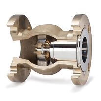
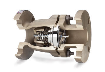
These check valves have a spring-assisted and non-slam design with applications in pressurized systems for preventing water hammer and in systems with exposure to extremely harsh conditions. With their use in brine, brackish water, and more, check valves are rated to withstand corrosion and deter marine life. They also feature a nozzle style for easy operation and require little maintenance.
Choose Reverse Osmosis Check Valves From DFT®
Reverse osmosis systems can purify water to make it safe for drinking, industrial processes, and pharmaceutical and food production. In those systems, check valves allow for safe and efficient water processing. For over 75 years, DFT® has innovated to provide its customers with in-line check valves and severe service control valves to fit their specific needs. Contact us today to learn more about our capabilities, or request a quote to start your order.
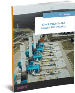
Check Valves in the Natural Gas Industry: Explore Our eBook
Natural gas demand rises in tandem with economic growth. For example, in the Utica and Marcellus Shale areas, the need for metering facilities and gas compression stations has expanded rapidly in recent years. Forecasts suggest that this ongoing infrastructure expansion should continue for the foreseeable future.

Six of the 6” 900# WCB/SS DFT® model PDC® Check Valves were the right solution to replace the piston check valves originally installed for this application.
DFT® Model PDC® Features:
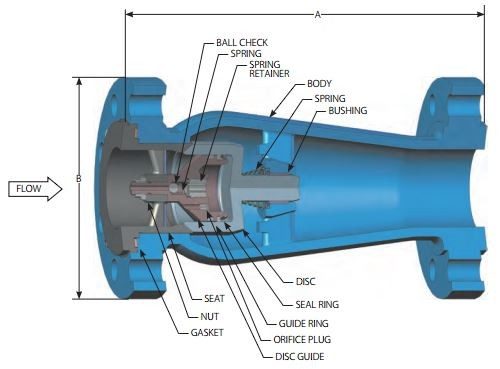
- ASME class 150 to 1500
- RF & RTJ flanged ends
- ASME B16.10 face-to- face dimensions
- Standard Body Materials:
- A216 WCB carbon steel
- A351 CF8M stainless steel
- A352 LCC low-carbon
steel
- Stainless steel trim
- Center-guided/dual-guided stem
- Spring assisted silent closing, non-slam
- Tight shutoff – lapped disc & seat
- Horizontal or vertical installation
- Protected spring
- Axial Flow
- Nozzle style
Access our eBook to Learn More about the Role of Natural Gas in Today’s World
Proper check valves reduce the likelihood of malfunctions and potentially catastrophic side effects in your natural gas system. Our new eBook, Check Valves in the Natural Gas Industry, explores:
- Which Check Valves Are Suitable for Natural Gas Applications?
- How long Do DFT® Check Valves Last?
- Construction of the PDC® and GLC® Check Valves
Additional Resources
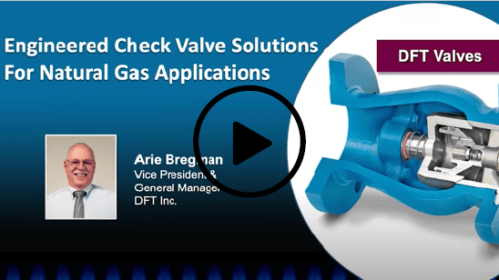
You can also download our free webinar, Engineered Check Valve Solutions For Natural Gas Applications to learn more about the important role of check valves and how to resolve flow issues and avoid failures.
The experts at DFT® can help you select the best check valves for your needs. If at any time you have additional questions, please contact us or request a quote.
Webinar Q&A: Engineered Valve Solutions for Natural Gas
As a follow-up to our webinar, Engineered Check Valve Solutions For Natural Gas Applications, we are sharing the questions we received from the audience. The answers are provided by host Arie Bregman, vice president and general manager of DFT® Inc. and a 35-year industry veteran, who is an active member in the U.S. Valve Manufacturers Association (VMA), serving as Chairman and on the group’s education, training, and technical committees.
When it comes to compressors and the gas applications they are used in, operational efficiency and safety are top priority. Reliable check valves are needed to protect compressors and other high dollar machinery. In our webinar, we discussed the many applications in which check valves are used throughout the journey from well to distribution, as well as how to resolve flow issues and avoid failures.
If you missed this webinar, you can now view it on demand. Simply click this link.
Below, our talented host answers questions regarding engineered check valves to help you find the right type and fit.
Q: You show 4 different valve styles as options. How do you choose the best valve?
A: Sometimes it’s dictated by the face-to-face requirements of the application. That being the case, then you’ll want a shorter pattern or longer pattern, if you don’t want to modify piping. If you have a new installation then a GLC, which is a non-standard face-to-face, may be a good solution. It has a one-piece body that may offer an advantage over a 2-piece body like the Excalibur. These are some important considerations. If we are talking about a reciprocating compressor, absolutely the PDC check valve is a very strong choice, probably the best choice in our family of products for that application. It is specifically designed for reciprocating compressor service and will give you a long lifetime, high-reliability product that can be custom tailored to be the ideal valve for the application.
Q: Can all DFT check valves be mounted in a vertical line? Why does flow up vs. flow down matter?
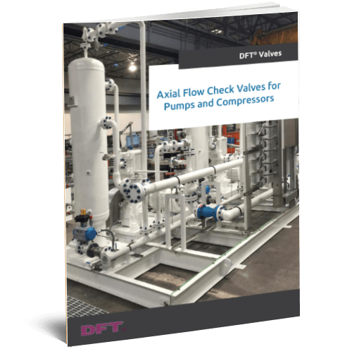
A: All DFT axial flow check valves can be mounted in a vertical line. All our valves have a spring opposing flow direction of the valve. So why does flow up vs. flow down matter? That gets to the consideration of the weight of the disc. If the flow is going up, the disc weight will help close the valve, so a lighter cracking pressure spring will be helpful. In the case of flow down, you absolutely have to compensate for the weight of the disc with a higher cracking pressure spring.
Q: In which applications would you use flanged valves and wafer style valves?
A: It’s easier to say where I would not use wafer style valves, and that would be temperatures below -50F and above +500F. In extremes of operating temperatures the flange bolts will be at a different temperature vs. the body of the valve which could lead to bolt relaxation or bolt over stress, either of which will lead to flange gasket leakage. If there is a risk of high temperatures from fire exposure, then stay away from a wafer style valve as well unless it is a lugged body design with tapped holes for the flange bolts. The inherently shorter bolts of a RF Flanged valve make it very preferable for high levels of gasket sealing and integrity.
Q: What kind of maintenance is required with this type of valve?
A: Maintenance requirements are based on the service conditions. Many, properly sized and selected DFT check valves can perform many years and even decades with no maintenance, but that requires investing the time up front and understanding the flow requirements and engineering the valve to work reliably under those flow conditions.
Q: How do your Excalibur, GLC and PDC valves compare to non-slam nozzle check valves?
A: These are all non-slam nozzle style check valves.
Q: Would it be possible to address the advantages of DFT valves vs. other brands?
A: DFT only manufactures axial flow check valves. This style of check valve has a demonstrated, significant advantage in reducing water hammer. DFT makes several styles of this axial flow design for short pattern requirements (wafer valves) up to and including flanged (RF and RTJ) and butt weld end ASME B 16.10 face to face requirements. DFT will also work with our end users to “engineer” the right valve for their application, whether that is due to low flow, low pressure drop, or special materials of construction. We will help you by providing the right valve solution.
Q: What is cracking pressure?
A: Cracking pressure is the pressure at which flow just begins. The fluid pressure has just overcome the forces of the spring and disc weight and the valve has just started to lose contact with the seat.
Q: How can I calculate the cracking pressure?
A: Cracking pressure is stated by the manufacturer and should be readily available by them along with the Cv flow characteristic, weights and dimensions.
Q: You mentioned that a lighter cracking pressure spring will slow down the closing rate of the PDC. Are there any other disadvantages associated with a lower cracking pressure spring?
A: Some of the other disadvantages of a lower cracking pressure spring, not thinking about whether we are talking gases or liquids, is if you have a vertical line flow down you may have to go to a higher cracking pressure spring just to compensate for the weight of the disc. For vertical line flow up, you may want a lighter cracking pressure spring because you are fighting gravity and not concerned about the weight of the disc in that case as it is helping to close the valve. If we are talking strictly liquid services, then lighter cracking pressure springs will make the valve less able to reduce water hammer.
Q: What is the delivery for these valves?
A: Standard valves are available from our inventory or our distributor’s inventory for fast delivery. Special requirements will require longer lead times. Please contact DFT for your specific requirements and product availability.
Q: In general, to prolong the service life of any valve is it advisable to have centrifugal compressors in any gas plant or refinery?
A: Prolonging the life of any valve in any service often requires engineering the valve specifically for optimum service life. With check valves this starts with doing the valve sizing calculations but also involves specifying the right valve for the application. Reciprocating compressors require valves designed for that service. The DFT model PDC is designed for very long life in recip compressor service. The choice of centrifugal vs. reciprocating compressor is usually driven by the pressure and volumetric needs balanced against lifetime installed cost for those two options.
Q: With the PDC, can the amount of damping be adjusted? For example, with more compressors can it be activated and the vibration changes?
A: No. The amount of damping is set by the orifice valve internal to the valve itself and cannot be adjusted.
Q: Does DFT have a service support rep in Canada?
A: DFT is represented by Triangle Fluid Controls throughout all of Canada. Please go to their web site at: https://trianglefluid.com/ for contact information.
Q: What does a stop do?
A: The stop limits the opening travel of the valve and should be designed based on the min, normal, and max flow conditions for the valve.
Q: Does the valve require certain straight pipe length upstream and downstream?
A: We recommend 5 x NPS upstream and downstream of the valve to ensure non-turbulent flow entering the valve and for non-turbulent flow to be restored after the media exits the valve. Oftentimes, sufficient space is not available in those cases, and dual guided valves should be selected. That is a valve where the closure mechanism is supported on both the upstream and downstream sides with a stem and bushing.
Q: Is this DFT Sizing software available for customer use?
A: Access to the DFT sizing software is on a limited basis. Please visit our website and contact the DFT Sales Representative in your area to discuss access to our sizing software, or our Sales Team can assist you with the sizing of check valves for your specific applications.
Q: How do you handle mixed phase flow in your sizing program?
A: When dealing with mixed phase flow in our sizing program, there are so many different variables on how much of the different phases exist in the medium. If it is simply a 5% or so of mixture, such as water vapor in a flow of steam, then adjust specific gravity and molecular weight a little bit. However, if there is a higher mixture of the two phases—ex. 50/50—then the technique is to size it as if sizing with only a gas, then size again as if only the liquid, then proportion the two results based on those 2 sizing outputs. If you do have this or a similar situation, we recommend contacting DFT to run the sizing and consult with you on what the proper sizing result should be for your particular flow situation.
Q: If you put a travel stop in a check valve, can it be removed or changed at a later date?
A: The travel stops we use can be removed from the valve or changed. It requires the valve to be taken out of the piping system. The valves we are talking about here are for natural gas applications and are not inline repairable. Both stops and springs can be removed or changed to go to a higher or lower cracking pressure. So, all that DFT can do to engineer a valve for an application can be changed or modified for changing conditions that you may experience with the application.
Q: Could it be a water-hammer hazard when the natural gas is flowing as a gas substance in a pressurized pipes network?
A: No. Water hammer is strictly a liquid or steam phenomenon.
Q: Is it possible to have water-hammer risk if the natural gas is flowing in gaseous form in a pressurized gas piping network?
A: No. Water hammer only occurs in liquid or steam service, where condensate is present in the lines.
Q: Are your slides available for us to download?
A: Yes, they are located in our Resource Section and can be accessed here.
For more than 75 years, DFT® Inc. has helped customers find and install the right check valves for their unique applications. To learn more about our valves, and how we can assist you, contact us directly.
What Is Cracking Pressure?
What Is Check Valve Cracking Pressure?
Cracking pressure refers to the inlet pressure level at which the first sign of flow is present. It can also be described as a measure of the pressure differential between the inlet and outlet ports of the valve when flow is initially detected. Specifically, cracking pressure is the least differential pressure that the valve experiences during flow.
Check valves are frequently used with liquids, but they are also found in many industrial applications handling media such as steam, gas, slurries, and mixed-phase flows. In relation to cracking pressure, pressure drop is another, somewhat related aspect of pressures within a valve to keep in mind. Pressure drop is the difference in pressure between both the valve’s inlet and outlet. Once the cracking pressure is reached, the valve starts to open, which facilitates the flow of the contained media. As the flow rate decreases, the valve then starts to shut.
The cracking pressure will depend on the check valve design. It’s usually measured in pounds per square inch (psi), pounds per square inch gauge (psig), bar or kPa (their metric equivalents), or both.
Why Is Understanding Cracking Pressure Important?
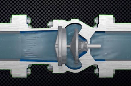
When choosing a check valve for a particular application, it’s important to know the valve’s cracking pressure. This specification is the initial indication of flow, but the valve won’t be fully open when it reaches cracking pressure. You’ll need to select the most appropriate valve with the right internal component design to achieve the required cracking pressure and overall pressure differential.
It’s also important to keep in mind that a check valve is designed to control flow in only one direction and is available with a specific normal cracking pressure. As the fluid flows through the valve and the pressure becomes greater than the cracking pressure, the disc moves off the seat, and the valve opens compressing the spring. When a check valve is oversized for the expected flow, it creates low flow (low velocity) conditions. Changing the spring to a lower cracking pressure can be one way to reduce chattering while improving the stability of the valve.
What Happens When the Incorrect Cracking Pressure is Selected?
Cracking pressure can have a significant impact on the compatibility of a check valve with its intended application. Certain issues can occur if the cracking pressure is too high or too low.
- Too high. High cracking pressure causes a higher pressure drop across the check valve. If the cracking pressure is too high, the valve may not open fully or at all. When the check valve isn’t fully open throughout normal flow, it may pop or chatter, which can lead to premature wear.
- Too low. Low cracking pressure can reduce the valve’s closing speed. If the cracking pressure is too low, the valve may also be unable to close entirely in the vertical flow down position because of the stem and disc weight overcoming the opposing force of the spring.
Get Check Valves with the Correct Cracking Pressure at DFT®
To ensure consistent flow and avoid premature wear, it’s important to choose the right check valve for your specific application. If you need help finding the correct check valve with the right specifications, DFT® carries a wide variety of check valve products to meet your application’s requirements. We offer a selection of threaded/socket weld check valves, vacuum breaker check valves, restrictor check valves, sanitary check valves, and more.
For help finding a check valve with the right cracking pressure for your needs, contact us today or request a quote to start your order.
Effective Check Valve Selection and Placement for Industrial Piping Systems
When planning a check valve installation, the primary goal is to achieve a valve and piping system that offers the longest service life at the lowest cost. Accomplishing this goal while also ensuring that the system operates effectively and efficiently requires several considerations.
As a world-class manufacturer of high-quality check and control valves, DFT® understands the challenges of choosing the optimal valve for a piping system. To facilitate the selection process for our customers, we put together the following guide outlining how to choose and implement the right valve.
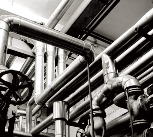
Principles of Piping Design
In general, optimal piping system designs follow three basic principles:
- There must be a 5-10x nominal pipe size (NPS) of straight pipe on either side of the valve, i.e., both the upstream and the downstream sides of the valve.
- The minimum pressure to open a check valve is referred to as the cracking pressure. However, to fully operate a valve, the system requires twice the differential pressure.
- While many styles of check valves will work in horizontal piping, only axial flow (“silent”) check valves are suitable for use in vertical piping. Whenever possible, a horizontal line is preferred since it rules out gravity, but vertical piping must be considered for flows that require up or down transport.
Common Piping Design Mistakes
Following the above principles facilitates the proper configuration of check valves in a piping system with minimal need for maintenance and maximum reliability. However, many industry professionals may find it challenging to navigate the nuances of pipeline design. Some of the most common mistakes made when designing a pipeline involve:
Valve Location
As mentioned in Principle #1, valves should have enough clearance—i.e., straight pipe—on either side from other pipeline components, such as pumps, elbows, expansion joints, and other valves, to function properly. When positioned upstream, these components can cause turbulence, which affects the performance of the check valve and can cause increased wear and, consequently, failure. The same can be said of other types of valves, such as ball valves and control valves; they perform best when the media flow is laminar, not turbulent.
Axial flow check valves can be installed close to the inlet of an isolating value if it is full port and fully open.
Flow Conditions
As outlined in Principle #2, there must be enough pressure to keep the valve fully open under minimum, normal, and maximum flow conditions. It is not enough to match the valve size to the pipe; it is necessary to do the sizing calculations to pick the right sized valve for the given flow conditions.
Vertical Pipe Runs
Avoid using swing check valves in vertical pipes. The downward flow keeps the valve open, and the upward flow leads to water hammer from the disc slamming against the seating. As specified by Principle #3, use only axial flow check valves in vertical pipes. The strong spring of the axial flow check valve avoids water hammer by ensuring that the valve closes before the reverse flow happens.
Choosing the Best Check Valve for Your Application
There are several factors to keep in mind when choosing a valve for a piping system. These selection considerations include:
Valve Location
As required by Principles 1 & 3 above, the location of a valve is important; horizontal piping is preferred for all valves except axial flow check valves, and there must be sufficient straight piping on either side of the valve.
Valve Size
Check valves remain open only when there is sufficient pressure in the line. Therefore, the pressure available with minimum flow must be considered along with maximum and normal flow conditions while selecting the valve. This is the requirement per Principle #2 above.
Valve Material
When choosing a valve material, the main focus is on choosing one that is compatible with the characteristics of the piping and requirements of the application (i.e., temperature, pressure, corrosion resistance, etc.). This generally results in the body material of the valve matching the flange material of the pipe. For example, a carbon steel line typically features a carbon steel valve body. Carbon steel is the most commonly employed valve material, with cast iron and stainless steel following close behind.
Types of Valves Used in Industrial Piping
Valves find use in a variety of industrial piping system applications. Typical applications include:
- Preventing reverse flow (check valves)
- Managing the flow of process fluids, including concentrated acids and bases
- Redirecting flow from one line to another
- Restricting flow for system balancing purposes
- Controlling cooling rates to regulate temperature
- Stopping flow during a system failure
Industry professionals employ a wide range of valves to fulfill the above functions, depending on the requirements and restrictions of their unique application. Some of the most common valve types used are:
- Check valves have a disc, stem, or a similar moving part that closes if the flow reverses or stops.
- Ball valves are the most common type of valve and feature a ball with a round hole in the center. When aligned with the pipe, the valve is ON. When turned 90°, it is OFF.
- Diaphragm valves are used for precise flow control, especially when the media contains solids.
- Flanged valves use bolts to secure the connection and a gasket to seal the joint.
- Gate valves turn flow ON and OFF with a vertical disc that moves up and down.
- Globe valves regulate flow with a disk that moves relative to a stationary ring seat.
- Needle valves are similar to a globe valve, but they use a tapered plug for finer flow control.
- Relief valves are safety valves that prevent excessive pressure buildup in the system.
- Wafer valves in general have a smaller footprint in the system.
In addition to the valves listed above, there are many other types available, each of which is suitable for varying industrial applications.
If you need a valve for your pipeline, DFT®, Inc. delivers. With over 75 years of experience manufacturing high-quality check valves and control valves, we can provide you with a valve solution that meets your needs. Check out our product page to find out about our valve offerings or contact us today with your questions or project specifications.


