Category Archive: Uncategorized
Common Causes of Swing Check Valve Failure and How to Diagnose and Resolve Them
Swing check valves use a hinged swinging disc to block and control the movement of fluid in a system. As they are used to prevent the reverse flow of fluids or gases, any failure can lead to leakage, loss of pressure, contamination, overflow, and, in the most severe cases, complete system failure. Below we discuss some of the most common causes of swing check valve failure, how to diagnose them, and appropriate solutions.
Why Do Swing Check Valves Break?
Swing check valves require reverse flow to close. This design causes them to malfunction or fail when subjected to insufficient or improper operating conditions. Understanding the cause of damage helps determine the best solution. Some of the most common causes of failure in swing check valves include:
Low Flow Application
In low flow applications, swing check valves are not able to maintain consistent flow when the system does not provide sufficient pressure. The insufficiency of pressure causes the disc to open and close frequently, causing excessive wear on the hinge pin and pivot arm where the disc may break off entirely. This can cause significant damage to downstream equipment.
Water Hammer
Water hammer refers to a pressure increase due to the sudden stop or change in the direction of the fluid traveling through the valve. It is a common occurrence with swing check valves, which rely on the reversal of fluid flow to close quickly. Over time, the repeated closing of the disc against the valve body may cause the disc to detach from the swing arm. Additionally, water hammer can cause other serious system issues, such as ruptured pipes and damaged fittings.
Improper Selection or Installation
When using a swing check valve in a fluid system, both proper selection and installation are key to safe and reliable system performance. The valve chosen should suit the system’s piping, material, orientation, flow direction, and flow rate to avoid inefficient performance and premature component wear. Additionally, when installing the valve, industry professionals should keep in mind positioning and orientation; the valve should not interfere or be influenced by other system components and should be oriented correctly in relation to flow. Swing check valves will not work in a vertical flow down application.
For additional information about how selection and installation affect valve and fluid system performance, watch DFT®’s webinar on Check Valve Installation and Piping Design Guidelines.
How to Diagnose Failing Swing Check Valves
The signs of a failing swing check valve are often audible. When the disc opens and closes repeatedly (because of low-pressure flow) or violently (because of water hammer), it emits a tapping or hammering sound, respectively. While the swing check valve may not be broken at this point, these noises mean that the disc, swing arm, and hinge pin are experiencing significant stress, which, over time, leads to wear and failure.
Swing check valves will also start to stick as they begin to break down. Sticking occurs when the valve is constantly tapping the top of the valve body and peening over the casting material. This repetitive action can grab the disc and prevent it from closing. These operating conditions can cause leakage or damage to other system components.
Replacing Failing Swing Check Valves

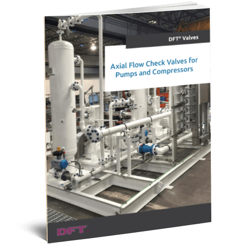
At DFT®, our team of valve experts will provide facts on how DFT®’s axial flow check valves provide safety and performance. Drawing from our extensive knowledge of valve selection and sizing, we determine which valve is right for your needs. For custom sizing, fill out and submit our datasheet.

For fluid systems that employ the use of swing check valves, we offer superior quality alternatives, such as our Excalibur® Silent Check Valve and DLC® Check Valve which ultimately prevent water hammer and can meet the demands of a low flow application, unlike other traditional swing check valves.
To learn more about our axial flow check valves that are replacements for swing check valves or our wide selection of non-slam check valves contact us or request a quote today.
Why Do DFT® Axial Flow Check Valves Inherently Reduce Water Hammer?
Hydraulic shock—more commonly known as “water hammer”—occurs when the flow within a pipe is suddenly forced to change direction, which creates a pressure wave that can be characterized by a loud knocking or banging sound. In piping and process systems, water hammer often happens upon closing a valve to stop or redirect flow. It’s important to take steps that will reduce water hammer or mitigate its effects, as repeated waves of pressure can cause significant wear on pipes and joints over time. Even without wear, a strong enough pressure wave may still burst weak threads or seals.
The best way to stop water hammer is to bring the flow to a stop before it reverses direction. This may be achieved using a valve, but the valve in question must be able to respond very quickly to the change in flow rate through the piping system. In this blog post, we will examine why the DFT® Axial Flow Check Valve is the best choice to halt water hammer of the 3 most common types of check valves:
- Swing check valves
- Double-door check valves
- Axial flow check valves
The time it takes for a valve to go from full open to full closed relies heavily on the distance the disc must travel. If the valve must respond quickly, it stands to reason that a shorter distance can be traversed in less time. The following illustration compares the travel distance for the above valve types.
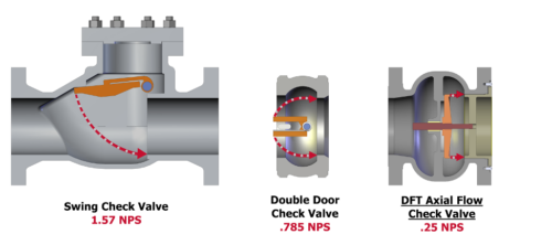
To simplify the explanation, we’ll use nominal pipe size (NPS) to represent the inside diameter (ID) of the pipe in all examples in this blog.
How Swing Check Valves Close
Swing check valves contain a disc that is hinged above the ID of the pipe, so the distance the swing check disc travels is ¼ of the circumference of the circle, where the radius of the circle is the NPS. If circumference is πD, then ¼ of this would be πNPS/4 or 1.57 NPS.
How Double-Door Check Valves Close
The disc used in a double-door valve is comprised of two halves hinged along the split. Each half of the disc travels through an arc, which can be represented by ½ NPS. Therefore, the distance that each half of the double-door disc travels is half the distance of the full disc in the swing check, or πD/8 or 0.785 NPS
How DFT® Axial Flow Check Valves Close
In general, axial flow check valve discs travel ¼ NPS (0.25 NPS) from a fully open position to a fully closed position. Given that a swing check valve disc must travel almost six times that distance to close, it stands to reason that an axial flow check valve disc can close much faster. By adding a spring to the disc, the disc can close before the flow reverses to avoid the water hammer effect.
Preventing Water Hammer With DFT® Axial Flow Check Valves
Water hammer poses a risk in most piping and process piping systems. Without proper solutions in place to mitigate hydraulic shock, these systems are at risk of bursts, leaks, or excess long-term wear. This makes it especially important to use check valves that can reverse flow without creating a damaging hydraulic pressure wave. To do this, the disc within a check valve must be able to close as quickly as possible.
DFT® Axial Flow Check Valves are designed with fast closure in mind. The spring-loaded discs in these valves go from fully open to fully closed with a significantly shorter travel distance than other check valve types. With this short distance and fast closure capabilities, the overall valve closure time is significantly reduced. This naturally mitigates the risk of water hammer.
For more information about our check valves and how they can prevent water hammer in your system, please request a quote.
New Technology at DFT
DFT® Inc. is proud to announce the implementation of new advanced robotics technology to streamline the manufacturing process at our Exton, PA headquarters.
This high technology robot provides the efficient production of lapped discs, which is an important manufacturing process at DFT, allowing for the tight metal-seated shutoff of our axial flow, spring-assisted check valves.
At DFT® we are constantly looking for process improvements to deliver cost-effective quality valves to our customers. Robotics provides the ability to perform repetitive tasks while providing superior quality, safety, and efficiency.
The productivity of this robot is 2.5X greater than our previous operator controlled mechanical lapping machine. In addition to increased productivity, ergonomic stress and employee safety is greatly improved because the robot does all the work and an operator only needs to occasionally load and unload pallets and replace lapping consumables.
Safety is a huge advantage with this new robotic process because the robot works in its own isolated work cell. This cell consists of physical barriers to keep personnel out as well as light curtains and a door sensor to instantly disable the robot should anyone attempt to enter the work cell during operation.
The success in lapping productivity has eliminated a bottleneck within production. DFT® has plans to improve other processes in the future with this safe and highly efficient technology without displacing any of our highly valued employees. For more information on DFT® products visit us online at dft-valves.com.
Check Valve Installation
Check valves play a critical role in preventing backflow and protecting sensitive equipment, pipes, pumps, and compressors. However, check valves can’t function at their best if they aren’t installed properly. Mistakes in installation can manifest in valve leakage or failure, compromising the integrity of the entire piping system.

Swing check valves, double-door check valve, or silent spring-assisted axial flow check valves, all control flow through a slightly different mechanism. Swing valves use a disc that swings in and out of the fluid stream while double-door valves use springs to close two “doors” to stop the flow. Spring-assisted axial flow valves use a disc and stem design and incorporate compression springs to close the valve before the fluid flow has reversed its flow direction. This is important because the quick closing nature of the axial flow design drastically reduces the possibility for water hammer—a dangerous malfunction where sudden pump shut down or an abruptly closing valve produces a hydraulic shock wave in the piping. In this guide, we’ll discuss ways to prevent water hammer and other common check valve problems.
When a Check Valve Is Necessary
Industry insiders call check valves the “misunderstood valves.” Many professionals simply don’t know when or how to use check valves appropriately, so they think that the entire category is unnecessary or ineffective.
So when is a check valve necessary? Typically, we recommend a check valve when there is the potential for the media being transported in the pipe to backflow, which can damage the system. Condensate pooling can also lead to water hammer. Installing check valves in condensate recovery lines prevents serious malfunction by automatically preventing backflow. In this way, the right check valve not only prevents serious problems like water hammer but also safeguards the entire process as well as the equipment installed in the piping.
Check Valve Installation

To experience the full benefits of a check valve, it’s critical to adhere to installation best practices. A simple mistake in fitting the valve can reduce efficiency at best or cause substantial damage at worst. Some key points to keep in mind include:
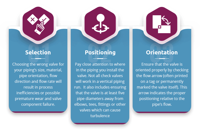
- Selection: Choosing the wrong valve for your piping’s size, material, pipe orientation, flow direction and flow rate will result in process inefficiencies or possible premature wear and valve component failure.
- Positioning: Pay close attention to where in the piping you install the valve. Not all check valves will work in a vertical piping run. It also includes ensuring that the valve is at least five pipe diameters away from elbows, tees, fittings or other valves which can cause turbulence
- Orientation: Ensure that the valve is oriented properly by checking the flow arrow (often printed on a tag or permanently marked the valve itself). This arrow indicates the proper positioning relative to the pipe’s flow.
Solutions to Your Check Valve Problems
Preventing check valve malfunctions like hammer pipe is critical to avoiding serious, costly damage to your pipes, valves or other expensive equipment. At DFT, we never want our clients to experience preventable system failure, which is why we’re sharing our expertise: in addition to this guide, we’ve put together a comprehensive webinar that expands on proper check valve installation and maintenance, providing expert guidance on piping design that works and lasts.
For specific questions about check valve selection for your application, contact our team. Whether you’re looking for a standard stock valve or a completely custom order, we’ll work with you to make sure you receive a functional, effective, and safe solution to your piping challenges.
DFT® Control Valve Webinar FAQ
DFT® recently held a webinar on severe service control valves. To follow up on the information we presented, here are some answers to questions we’ve received.

Are you coping with corrosive aggressive services? Which materials do you use?
Our Ultra-Trol valve is designed to withstand corrosive media with a combination of metallurgy and controlling fluid conditions. It has replaceable liners, as well as wear-resistant materials, including Stellite, 440C, and Tungsten carbide.
How soon you can deliver a valve after receiving the PO?
We can deliver a valve within 10-12 weeks of receiving an order. Depending on our factory capacity at the time of the order, we can often accommodate faster delivery times.
How can digitalization help you predict integrity damage of a valve to take preventive measures before is too late?
As a preventive measure, we recommend a series of initial inspections. This will identify the wear rate, so you can predict integrity damage.
What is the preferred range of operation of a valve?
For the HI-100, the effective range of operation is between 15-90% open. The preferred range is between 30-85% open.
How do you select a valve?
To ensure you get the right valve, they are sized by DFT® engineering. To do that, they take into account temperature, pressure, fluid type, and flow.
What type of valve characteristic curve is preferred (e.g. equal percentage, linear, etc.)?
For the HI-100®, the valve trim characteristic is linear.
What is the max CV/min CV preferred value when selecting a valve?
DFT® engineering accounts for inlet pressure, orifice size pressure drop, and valve flow path to select a trim package that will result in max CV/min CV preferred value within the range of 30-85% full open.
What is the ease provision of trim replacement in Venturi style?
The HI-100® Straight-Through Venturi Style Control Valve is an in-line repairable valve, so replacing the trim requires a few simple steps. First, remove the valve bonnet, which will enable you to remove any internal component. The trim can be removed without any special tools. When the trim has been replaced, reassemble the bonnet. Be sure to follow the disassembly and reassembly instructions in the DFT® HI-100® maintenance manual.
Do you cover also 3-way valves and angle valves? Where are they used and what are their characteristics?
For more information on valve types and sizes we offer, take a look at our website. You’ll find DFT® catalogs, including those for Check Valves, HI-100® Severe Service Control Valves, and LSV-100® General Service Control Valves.
Catalogs have information on valve sizes, types, and material options. DFT® engineering sizes every HI-100® valve based on application data provided by the end user. You can find an application data sheet on page 13 of the DFT® HI-100® catalog or download the PDF here.
Can your valves be 4-20mA or 0-10V modulated and if yes, how does it work?
The controller package in the HI-100® valve/actuator/accessory assembly contains 4-20mA modulator capability. Although DFT® doesn’t manufacture controllers, we do mount them as a part of our complete assembly package. We are able to support a number of control protocols with a range of actuator and controller packages.
How do you isolate a valve during operation?
As it is a modulating control valve, the DFT® HI-100® can achieve Class V shutoff. This is a tight shutoff which is specially designed for isolation service, but not an isolation valve. For systems that require this function, we recommend that an isolation valve is installed upstream from the HI-100®.
Is the ball in the Venturi free to rotate in any position during operation?
During the initial opening of the valve, the HI-100® ball rotates less than 90 degrees, and then it drops during valve closure. As a result, the ball does not contact the seat in the same position, which reduces wear on the ball.
How do you deal with valves operated in parallel (e.g. 50-50% or other)?
In some cases, valves must be operated in parallel, known as “split range” control. One example is a 50-50% arrangement, where two valves each handle half of the total flow. In this case, the valve positioners are configured so they will accept 4-12 ma and 12-20 ma, respectively. This adapts to situations dealing with a large range of flows.
Does DFT® have motorized control valve with fast reaction time (<1sec)?
For a motorized control valve with fast reaction time, linear actuators that are capable of driving DFT® control valves in less than a second are available.
Price-wise, what is the difference when comparing a globe valve to the Venturi style of the same size?
If you’re comparing the prices of a globe valve with the Venturi style valve of the same size, there are a few factors to consider. Venturi style control valves can generate CVs that are 2-3 times greater than a globe control valve of a similar size. As such, you would need a much smaller sized Venturi style control valve in the same environment as a larger globe style valve. Since the Venturi style valve can provide much greater flows, it is more accurate to compare the price of a Venturi style control valve that can manage the goal CVs against the price of the globe style control valve that can achieve the same CVs.
How do you evaluate the opening/closure time for critical valves?
To evaluate the opening and closure time for critical valves, stroke times are specified in the quote. They will be accounted for in the design process, and we will test them in the factory before shipment.
How do you replace the wear bushings in case of a welded end connection? Can those be accessed by removing the bonnet?
The HI-100® is an inline repairable valve. First, remove the valve bonnet, which will give you access to all internal components. The wear bushings can be removed and replaced without using any special tools. Once that’s done, reassemble the bonnet. Be sure to follow the disassembly and reassembly instructions in the DFT® HI-100® maintenance manual.
See What DFT® Can Do for You
DFT® has been offering the best in valves since 1943. If you have additional questions or would like more information about one of our products, please contact us.


